Water treatment controllers approximate the TDS of the water through the use of a conductivity measurement. As the amount of dissolved solids in the system increases, so do the conductivity readings.
Conductivity controllers pass a low-voltage AC signal across the conductivity electrodes to determine the conductivity of the water. When other voltages are present in the water stream, the problem manifests itself as erratic or “pegged” conductivity readings on the controller. This is often accompanied by a discoloration and deterioration of one or both of the conductivity electrode surfaces. The electrodes may appear darkened or even charred.
Though the symptoms are easy to identify, the sources of stray voltages in circulating water systems are often hard to pinpoint and eliminate. Typical sources of stray voltages include improperly grounded devices that share a piping or wiring connection with the conductivity controller (re-circulating pumps, feedwater pumps, chillers, boilers, etc.).
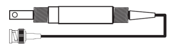
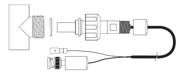
To determine whether or not problematic conductivity readings are caused by external sources, simply remove the conductivity electrode from the system piping and place it in a cup of water. If the conductivity reading is stable and accurate, then the problem lies externally to the controller.
Once you have identified that a stray voltage does indeed exist in the system, a qualified electrician should be called in to examine the system. Given the wide array of components that share piping or wiring with the controller, the source of the stray voltage is often never found. If the stray voltage cannot be eliminated, steps should be taken to minimize the effect on the conductivity controller. Try the first suggestion listed below and test the results before attempting the second suggestion. It may not be necessary to perform both steps.
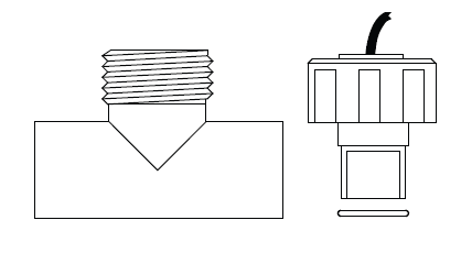
- Ground the system piping to the conductivity’s circuit ground. Tie a piece of wire around the pipe near the conductivity probe and secure the other end to the appropriate circuit ground inside the controller (consult the manufacturer for specific wiring instructions).
- Install a capacitor (10-microfarad, non-polarized) in series with each of the probe’s conductivity wires (red & black). Be sure to use non-polarized capacitors as the polarized version will likely wear out prematurely.
If neither of the above recommendations works, the problem is beyond the scope of our troubleshooting capabilities. Consider using a programmable cycle timer to blowdown the boiler at a regular interval to keep the TDS below scale forming levels. Existing conductivity controllers can be converted to cycle timers in the field by disconnecting the conductivity probe. The controller will then ignore the conductivity control feature since it will read zero at all times.
Grounding procedure for suspected DC voltage:
1. Secure one end of a grounding wire to the water pipe.
2. Remove the front panel (logic board) of the controller and run the other end of the wire through one of the controller’s gland fittings.
3. Secure the loose end of the wire to either terminal labeled “Ground” shown in the logic board diagram below.
4. Replace the front panel of the controller.
If these steps do not eliminate the problem, try the following procedure:
Installing 10μF NP capacitors in the conductivity circuit:
1. Remove the front panel (logic board) of the controller.
2. Remove the red and black conductivity probe wires from their terminal blocks.
3. Insert one leg of the first 10μF non-polarized capacitor into one of the open conductivity probe terminal blocks and secure (no polarity) – see diagram below.
4. Connect the other leg of the first capacitor to one of the probe wires you disconnected in step #2. Make sure the connection is secure.
5. Repeat this process for the other capacitor using the other empty terminal block and other conductivity probe wire.
6. Remove the white and green conductivity probe wires (temperature) if you haven’t done so already.
7. Replace the front panel of the controller.